Page updated:
March 19, 2021
Author: Curtis Mobley
View PDF
Fresnel Equations for Polarization
This page shows how polarizied light is reflected and transmitted by a level air-water surface. The geometry is the same as for the Level 1 discussion of Fresnel reflectance and transmittance of unpolarized light by a level sea surface. Now, however, the state of polarization of the incident light is described by a four-component Stokes vector, as described on the page on Stokes Vectors. Consequently, reflection and transmission by the surface are described by matrices.
The state of polarization of a light field is specified by the four-component Stokes vector, whose elements are related to the complex amplitudes of the electric field vector resolved into directions that are parallel () and perpendicular () to a conveniently chosen reference plane. However, there are two versions of the Stokes vector seen in the literature, and these two versions have different units and refer to different physical quantities. The coherent Stokes vector describes a quasi-monochromatic plane wave propagating in one exact direction, and the vector components have units of power per unit area (i.e., irradiance) on a small surface element perpendicular to the direction of propagation. The diffuse Stokes vector describes light propagating in a small set of directions surrounding a particular direction and has units of power per unit area per unit solid angle (i.e., radiance). It is the diffuse Stokes vector that appears in the vector radiative transfer equation. The differences in coherent and diffuse Stokes vectors are rigorously discussed in (Mischenko, 2008).
For either air- or water-incident light, denotes the diffuse Stokes vector of the incident light, is the reflected light, and is the transmitted light. Angles , , and are the incident, reflected, and transmitted directions of the light propagation measured relative to the normal to the surface. For a level surface, , , and all lie in the same plane.
There are four matrices to describe reflection and transmission: describes how air-incident light is reflected by the water surface back to the air, describes how air-incident light is transmitted through the surface into the water, reflects water-incident light back to the water, and transmits light from the water into the air. However, because , , and are coplanar, scattering by the level surface does not involve rotation matrices as does scattering within the water body. (Or, from another viewpoint, the incident and final meridian planes and the scattering plane are all the same, the rotation angles between meridian and scattering planes are 0, and the rotation matrices reduce to identity matrices.)
The reflection and (especially) transmission of polarized light by a dielectric surface such as a level water surface are rather complicated processes, and the literature contains a number of different (and, indeed, sometimes incorrect) mathematical formulations of the equations. The formulas given in (Garcia, 2012) are used here. Note, however, that although the equations in (Garcia, 2012) are correct, some of his derivations and interpretations are incorrect, as explained by (Zhai, et al. (2012). Both papers must be used to understand the equations now presented. The equations in Garcia will be referenced by (G21) and so on; the corresponding equations in (Zhai et al. (2012) will be referenced as (Z5), etc.
The reflectance and transmittance matrices have a general formulation for the interface between any two dielectric media a and b. Let be the index of refraction of medium a and be that of medium b. In general and are complex numbers, but for the air-water surface we take and to be real indices of refraction. For reflection, the reflected angle equals the incident angle . For transmission from a to b, the transmitted angle is given by Snel’s law, , or
| (1) |
For water-incident light, and , in which case the transmitted angle becomes undefined beyond the critical angle for total internal reflection, which for water is . For water-incident angles greater than the incident light is totally reflected back to the water and no light is transmitted to the air.
Let denote the reflectance matrix for light incident from medium a and reflected back by medium b. thus represents either or . Likewise, let denote the reflectance matrix for light incident from medium a and transmitted through the surface into medium b. thus represents either or .
With these preliminaries, the reflectance matrix is (G10)
| (2) |
Here denotes the real part of and is the imaginary part.
The transmission matrix is (G11 or Z3)
| (3) |
The components of these equations are given by (G7):
The factor is defined below in Eq. (23). In general, the indices of refraction are complex numbers and these equations must be used. However, for real indices of refraction, the matrix elements can be simplified at the expense of having a special case for water-incident angles greater that the critical angle.
Define
| (8) |
Then for the case of air-incident light, i.e., , or water-incident light with the incident angle less than the critical angle, i.e., and , the equations yield the real forms (G14 and G15)
It should be noted that for the case of normal incidence, , both and reduce to
| (17) |
This gives a reflectance of for , for both air- and water-incident light.
For the case of total internal reflection, i.e., and , the following equations are to be used (G22):
and all elements of the transmission matrix elements are 0:
| (22) |
Finally, the all-important transmission factor in Eq. (3) is given by
| (23) |
when computing the transmittance for diffuse Stokes vectors. These equations give everything needed to describe reflection and transmission of polarized light by a level sea surface.
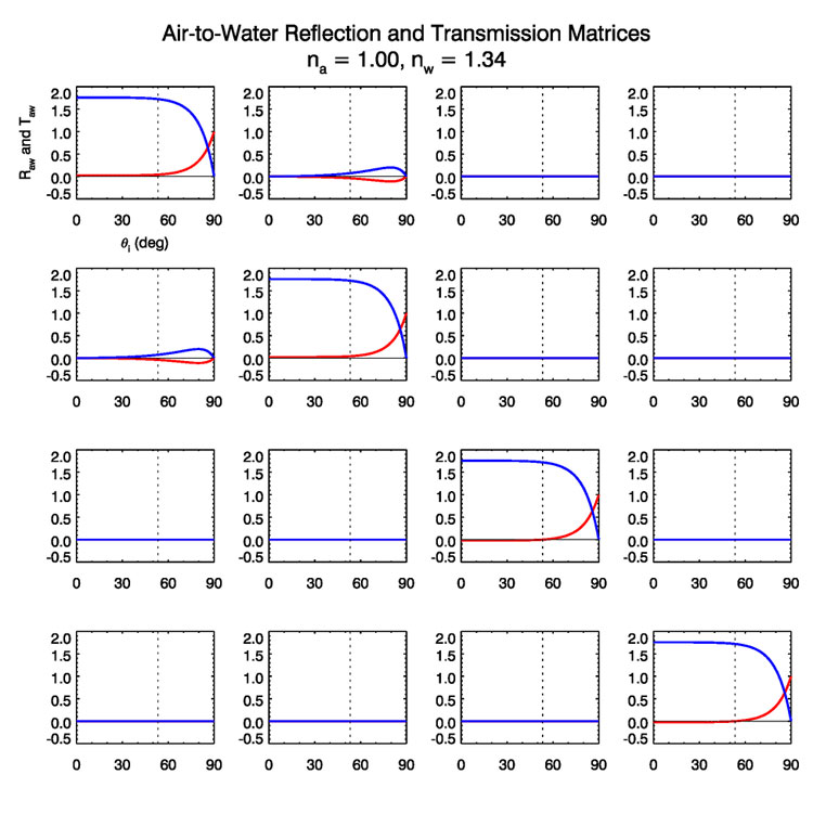
Figure 1 shows the and matrices as a function of incident angle for and . The (1,1) matrix elements are shown in the upper-left plot, and the (4,4) elements are in the lower-right plot. The red curves are and the blue curves are . The reflectance curve for is the Fresnel reflectance for unpolarzed light as given in the section on Fresnel formulas for unpolarized light: it starts at 0.021 for normal incidence and , and rises to 1 at grazing incidence. The transmission curve for on the other hand may look incorrect because it has values greater than one. Its maximum value at normal incidence is
| (24) |
However, this value is indeed correct and is a consequence of the fact that we are now dealing with a diffuse Stokes vector with units of radiance, and the law for radiance applies. The curves in Fig.(1) agree exactly with the corresponding plots in (Garcia, 2012) (his Figs. 1-3).
If we were dealing with coherent Stokes vectors with units of irradiance, then the factor of Eq. (23) would be
| (25) |
The transmittance for normal incidence then would be , which with the reflectance sums to one (and also sums to one for all other incident angles). As noted elsewhere, it is the Law of Conservation of Energy, not the law of conservation of radiance.
The vertical dotted line in Fig. (1) shows the location of Brewster’s angle,
| (26) |
which is in the present case. At this angle, , and . In the present case at , and the reflection process becomes
| (27) |
Thus, at Brewster’s angle, unpolarized incident radiance is totally horizontally polarized upon reflection.
It should also be noted that the non-zero means that unpolarized radiance becomes partly horizontally polarized upon transmission through the surface.
Figure (2) shows and as reduced scattering matrices, i.e. after dividing each element by its (1,1) component. These plots show more clearly the behavior of the matrix elements at Brewster’s angle. These curves agree exactly with the corresponding plots in (Kattawar and Adams (1989) (their Fig. 4).
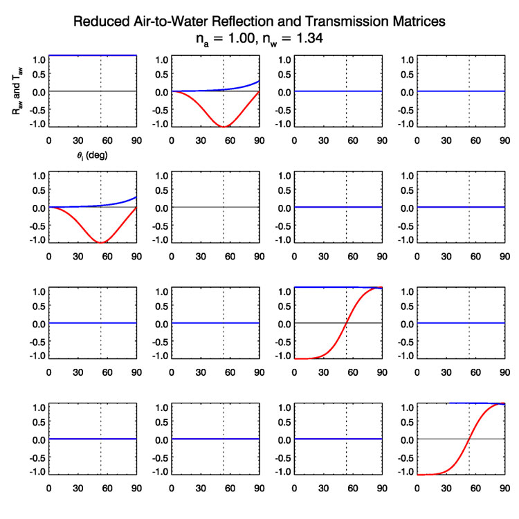
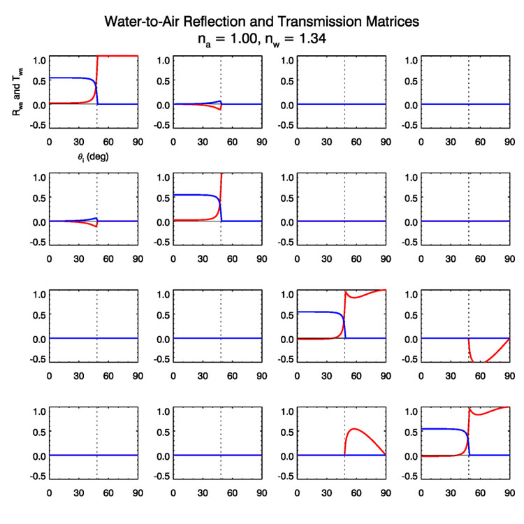
Figure (3) shows and . The vertical dotted line is at the critical angle for total internal reflection, which in the present case is . For angles less than the critical angle, the transmission is never more than about 0.54. This again shows the n-squared law for radiance. In going from water to air, the in-water radiance is decreased by a factor of when crossing the surface because the solid angle in air is greater than that in water by a factor of . The (1,1) elements show that beyond the critical angle there is no transmission and total reflection. These curves agree with the corresponding plots in (Garcia (2012) (his Figs. 4-6).
Figure (4) shows the reduced water-to-air matrices. These curves agree with the corresponding plots in (Kattawar and Adams (1989) (their Fig. 5. The signs of the and elements are reversed in the original Fig. 5, which had a sign error.).
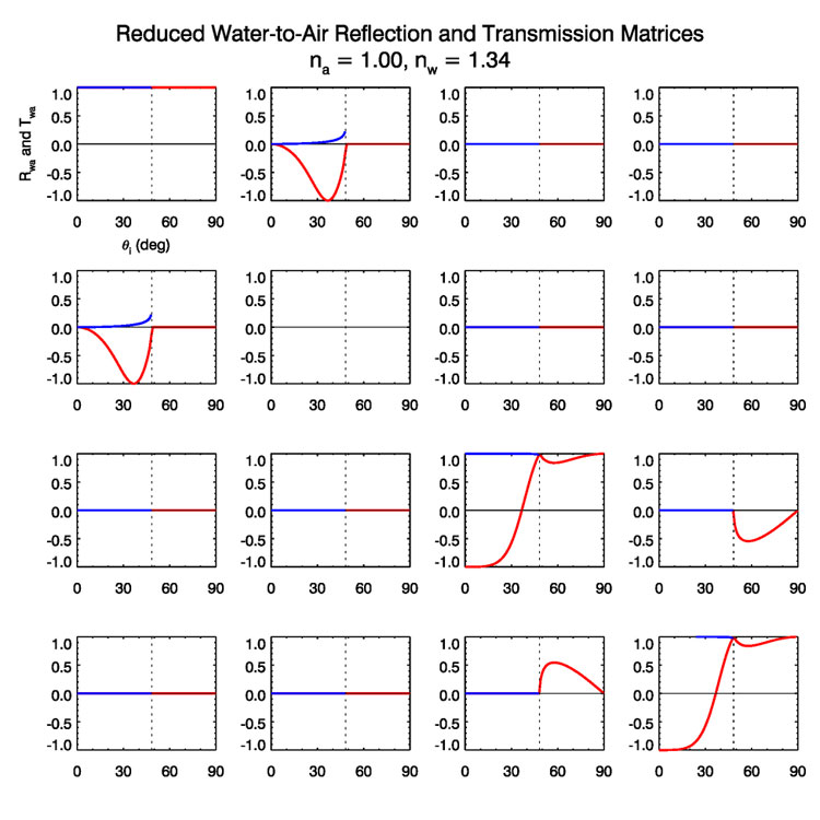
The non-zero matrix elements of course depend on incident angle as seen above, but also depend weakly on the wavelength via the wavelength dependence of .
 See comments posted for this page and leave your own.