Page updated:
March 16, 2021
Author: Curtis Mobley
View PDF
Contrast
The luminance transfer equation developed on the previous page gives us the theoretical structure needed to begin discussing the topic of visibility. The development here will be in terms of luminance, as is appropriate for a human observer.
The Luminance Difference Law
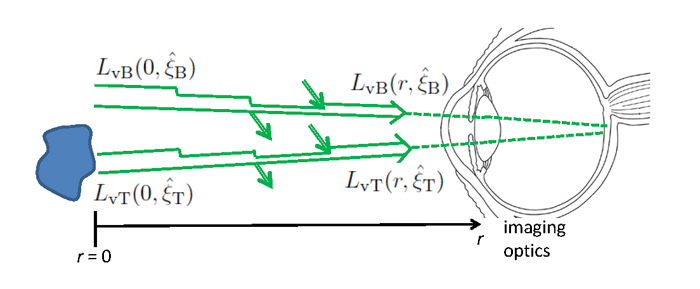
Figure 1 illustrates the quantities involved with viewing an object through an absorbing and scattering medium under ambient daytime illumination. The object, usually called the target, is being viewed against a background. The luminance leaving the surface of the target and heading in the direction of the observer is (subscript “v” for visual and “T” for target). The luminance of the background immediately adjacent to the target is , where “B” is for background. These two luminances eventually reach the observer, where they are focussed onto different points of the retina (or, in an instrument, perhaps onto adjacent pixels of a CCD array).
Now assume that
- 1.
- The object is small and is illuminated by ambient daylight.
- 2.
- The luminance leaving the target does not significantly affect the ambient luminance that is present in the absence of the target, and
- 3.
- The two directions and are almost parallel, i.e. , so that the absorbing and scattering losses and additions to each beam are the same between the target area and the imaging system. Likewise, any internal sources are the same along each path.
Equation (4) of the luminance transfer equation page gives the equation governing propagation of luminance at any point along either path:
Because the ambient luminance distribution, the IOPs, and any sources are assumed to be the same for each path, the path luminance term , which describes broad-band scattering into the beam, and the source term , will be the same for both background and target luminances. Thus the two luminances obey
Subtracting Eq. (3) from Eq. (2) gives
This equation has the solution
In most practical situations, can be assumed constant along the viewing path (in the ocean, a few tens of meters at most), in which case this solution reduces to
| (4) |
Even though each radiance and individually depends on all photopic IOPs, their difference depends only on the photopic beam attenuation . This is known as the Luminance Difference Law (e.g., Preisendorfer (1986)).
The Law of Contrast Reduction
Now define the apparent visual contrast between the target and background as seen at distance as the difference in the target and background luminances normalized by the background luminance:
| (5) |
From Eq. (4), this can be rewritten as
This result holds for any viewing direction (for the assumptions of the derivation).
is the inherent visual contrast, i.e., the contrast of the target against the background as seen from zero distance. If the target is darker (lighter) than the background, is negative (positive). The apparent contrast keeps the same sign as as increases and approaches zero. For a black target, , and . For a black background, , and the inherent contrast becomes infinite. This situation (such as viewing a distant light at night) violates the present assumption of viewing an object in ambient daylight, and a different analysis is required.
Looking horizontally, the background radiance is independent of the viewing distance if the water is horizontally homogeneous. In this case, the Eq. (7 reduces to
| (8) |
Other viewing directions may also satisfy . An exception to would be looking upward at a target near the sea surface from a larger depth. The downwelling radiance could then be much brighter at the target depth than at the viewing depth.
Either of equations (7) or 8) is called the Law of Contrast Reduction or Law of Contrast Transmittance.
For horizontal viewing and a black target, experience shows that the target can be detected at a visual range when . (You can find recommended minimum contrast values from 0.01 to 0.05 in the literature.) Equation (8) can be solved for this minimum contrast to get the corresponding visual range:
| (9) |
This result, originally developed for viewing dark targets in the atmosphere, is known as Koschmieder’s law. In very clear water (), , which limits underwater visibility to less than 100 m. In a very clear atmosphere, visibility can be as much as 200 km.
The limiting value of 0.02 for the minimum contrast depends somewhat on factors such as the angular size of the target, whether the target is fading from view as increases or appearing out of the background as decreases, and on the observer’s visual acuity. In any case, this result is in rough agreement with the experiments of Zaneveld and Pegau (2003) showing that the visibility range of a black Secchi disk 0.2 m in diameter, when viewed horizontally against the background ocean, is about
This range corresponds to a minimum detectable contrast of about 0.01, rather than 0.02. Airports use a value 0.05, which gives an added safety factor when judging how far a pilot can see.
The contrast defined by Eq. (5) is called the Weber contrast. This is a suitable measure of contrast when viewing a small object against a background. If the target has a pattern of bright and dark features with roughly equal areas of each (like the stripes on a zebra), then a more suitable measure of contrast is the Michelson contrast:
where and are respectively the maximum and minumum luminances for the bright and dark areas of the target.
 See comments posted for this page and leave your own.