Page updated:
May 5, 2021
Author: Curtis Mobley
View PDF
Energy Conservation
When making or computing radiance or irradiance measurements in the ocean, it is sometimes hard to verify that energy is being conserved. This is equally true when looking at the output from a numerical model such as HydroLight. Confusion most often arises when comparing measurements made just above and below the sea surface and observing that the measured (or predicted) radiances do not seem to “add up” correctly. To resolve such confusion, first note that it’s the Law of Conservation of Energy, not the law of conservation of radiance or irradiance. We must therefore express the law of conservation of energy in terms of radiance or irradiance as appropriate to the measurements being made.
Energy Conservation Within the Water
Within the water column, if there are no internal sources such as bioluminescence or inelastic scatter contributing to the wavelength of interest, conservation of energy is expressed in terms of irradiances by Gershun’s law:
| (1) |
Here is the absorption coefficient, is the scalar irradiance, and and are the downwelling and upwelling plane irradiances. This equation can be illustrated using numerical results generated by htmladdnormallinkHydroLight/view/radiative-transfer-theory/level-2/hydrolight. A run was made with the sun placed at a 60 deg zenith angle in a clear sky; the wind speed was , and the water was infinitely deep. The absorption coefficient was set to , the scattering coefficient to , and a Petzold “average-particle” phase function was chosen. (The run used HydroLight’s “Constant IOPs” submodel for these inputs.) No internal sources were included in the run. Table shows the computed irradiances at depths of 5.00 and 5.01 m. Closely spaced depths are used to illustrate Eq. eqrefEq:Gershun so that the depth derivative can be accurately approximated as a finite difference and the scalar irradiance can be taken as the average of the values at 5.00 and 5.01 m.
| depth (m) | |||
| 5.00 | 0.51833 | 0.013151 | 0.32613 |
| 5.01 | 0.51749 | 0.013129 | 0.32559 |
Using these values in the finite difference approximation of Eq. (1) gives
The absorption coefficient as computed from the irradiances via Gershun’s law is the same as the one used as input to the run, so HydroLight is conserving energy in its in-water solution of the radiative transfer equation. (HydroLight also conserves energy if internal sources are present. Demonstration of that requires adding an appropriate source term to Gershun’s equation; see Eq. (6) of the Gershun’s Law page or Light and Water (1994) Eq. 5.34.) Such accuracy cannot be expected with real data because of imperfect instrument calibration and other sources of error such as Raman scatter (an internal source not accounted for in Eq. eqrefEq:Gershun, which will always be present to some degree during daylight measurements. Nevertheless, Gershun’s law can be a useful way to retrieve absorption coefficients from in-water radiance or irradiance measurements, as seen in papers by Voss (1989) and Maffione et al. (1993).
Energy Conservation Across the Air-Water Surface
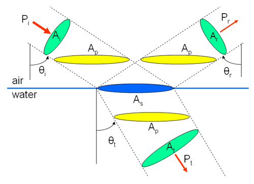
The situation is more complicated when considering energy conservation across the air-water surface. Consider a collimated beam of light incident onto a level sea surface. Part will be reflected and part will be transmitted into the water. Figure 1 shows this geometry and various quantities needed to express conservation of energy at the surface.
Conservation of energy (or equivalently, power) across the surface requires that
| (2) |
where is the power in an incident collimated beam of cross section , is the power in the reflected beam of cross section , and is the power in transmitted beam of cross section . These beam cross sectional areas are shown in green in Fig. 1. The beam of incident power illuminates a horizontal area of the level sea surface (shown in blue).
Energy conservation in terms of plane irradiances
Conservation of energy can be expressed in terms of incident (downwelling), reflected (upwelling), and transmitted (downwelling) plane irradiances using the horizontal projections of the beam cross section areas. Recalling that plane irradiance is power per unit horizontal area, Eq. (2) becomes
where the horizontally projected areas corresponding to each beam are shown in yellow in Fig. 1. Since each beam has the same horizontally projected area, this equation reduces to just
Equation (3) is conservation of energy across the surface expressed in terms of plane irradiances for a collimated incident beam.
Energy conservation in terms of scalar irradiances
To express Eq. (2) in terms of the scalar irradiances, first recall how is obtained from the radiance (Eq. 6 of the Geometrical Radiometry page):
For a collimated incident beam in direction , we can write the radiance in terms of the beam irradiance and a Dirac delta function to get
where is the incident irradiance on the beam cross sectional area; . Similar equations hold for the reflected and transmitted scalar irradiances. These beam cross sectional areas are shown in green in Fig. 1. Thus Eq. (2) becomes
or
after noting that by the law of reflection. By geometry, the ratio of areas is just . can be written in terms of using Snell’s law, , where is the real index of refraction of the water. Equation (4) then becomes
Equation (5) is conservation of energy expressed in terms of scalar irradiance for a collimated incident beam.
To illustrate Equations (3) and (5) with HydroLight output, a run was made with the sun at a zenith angle of in a black sky, in order to obtain a collimated incident beam. The incident onto the surface was set to 1. The sea surface was level (zero wind speed), and the water index of refraction was . The scattering coefficient within in the water was set to zero, so that upwelling light from the water column would not confuse the illustration of energy conservation across the sea surface itself. The absorption coefficient was set to . (These runs used HydroLight IOP model “Constant IOPs” and the “idealized sky model”).
The computed irradiances just above and below the surface are shown in Table . The upwelling irradiances in the water are zero because there was no scattering by the water and the bottom was infinitely deep. These computed irradiances satisfy Equations (3) and (5), showing that HydroLight conserves energy across the surface.
| location | ||||
| in air | 0.12690 | 2.0077 | 0.063209 | 1.0000 |
| in water at depth 0 | 0.00000 | 1.2277 | 0.0000 | 0.93693 |
A run was then done with a heavily overcast sky to generate a diffuse sky radiance pattern with the sun’s location not discernable. The wind speed was to generate a non-level sea surface. The resulting irradiances are shown in Table
| location | ||||
| in air | 0.18863 | 1.7764 | 0.050456 | 1.0000 |
| in water at depth 0 | 0.00000 | 1.1430 | 0.0000 | 0.94954 |
As before, these plane irradiances satisfy Eq. (3). However, the scalar irradiances do not satisfy Eq. (5). The reason is that Eq. (5) must be applied for each particular incident direction of the diffuse sky radiance, in order to correctly compute the angle factor seen in Eq. (5). If this is done one direction at a time (with the sun in a black sky), each individual incident direction satisfies Eq. (5) just as in the previous example. Thus energy is conserved across the surface “beam by beam,” hence in toto, even if it is not obvious from the total scalar irradiances.
A further complication occurs when the water body has scattering. To illustrate this, the scattering coefficient was set to and a Petzold “average-particle” phase function was used in the previous simulation. The computed irradiances were then
| location | ||||
| in air | 0.21264 | 1.7764 | 0.062372 | 1.0000 |
| in water at depth 0 | 0.07922 | 1.2046 | 0.031115 | 0.96873 |
Now even the plane irradiances appear to violate conservation of energy, Eq. (3). The reason is that and in air contain both surface-reflected radiance (as before) and radiance transmitted upward through the sea surface. Likewise, and in the water contain both downward transmitted irradiance (as before) as well as upwelling radiance that has been reflected back downward by the surface. This makes it appear at first glance that the irradiances do not add up correctly, even though energy actually is conserved across the air-water surface. The effects of both the surface itself and the water body can be accounted for simply by tallying the plane irradiances incident onto and leaving the surface from above and below:
Equation (6) expresses conservation of energy for the surface plus water body, for any conditions of incident lighting and water IOPs. The irradiances seen in Table () satisfy this equation.
Energy conservation in terms of radiance
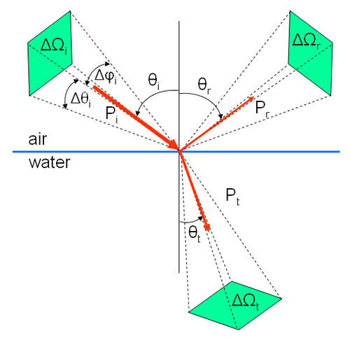
Another complication occurs when expressing conservation of energy across the surface in terms of radiance. Now it is necessary to account for changes in both the beam cross sectional area and in solid angle when going across the surface. When interpreting HydroLight output, it must be remembered that the computed radiances are averages over “quads” or solid angles of finite size, as discussed on the HydroLight page. Such quads are represented by the green areas in Fig. (2).
Remembering that radiance is power per unit area per unit solid angle, Eq. (2) can be written as
or
after noting that and by the law of reflection. As noted before, . The solid angles are given by , where the angle ranges are determined by the and boundaries of the quads. Thus the last equation becomes
| (7) |
since for the HydroLight quad layout. These angle factors must be evaluated for the particular quads associated with the incident and transmitted beams.
Consider again the previous case of the sun in a black sky at , a level water surface, and no scattering. The incident and reflected HydroLight quads are centered at 60 deg and extend from 55 to 65 deg. Snell’s law gives the transmitted direction as . Thus the transmitted radiance is contained in the HydroLight quad centered at 40 deg and extending from 35 to 45 deg. For the transmitted quad, for example, . Evaluating the angle factors in Eq. (7) for these quads gives
| (8) |
The corresponding computed quad-averaged radiances for this run were , , and . These radiances satisfy Eq. (8). Thus energy expressed as radiance is conserved beam-by-beam across the water surface.
We have seen that conservation of energy across the sea surface can be expressed in various ways in terms of radiance and irradiances. However, those expressions are often written for collimated incident beams and consider only the surface itself (Eqs. 3, 5, and 7). It is therefore not always obvious that energy is conserved for the entire surface plus water column when looking at data or simulations for realistic conditions of sky radiances and water IOPs. In general, Eq. (6)should be used to check conservation of energy across the sea surface with measured or modeled plane irradiances.
 See comments posted for this page and leave your own.