Page updated:
May 11, 2021
Author: Curtis Mobley
View PDF
Problem Formulation
The introduction to atmospheric correction on the previous page illustrated the nature of the problem. It is now time to define the problem quantitatively.
The total radiance measured by a satellite-borne sensor at the top of the atmosphere (TOA) comes from contributions by atmospheric scattering, ; Sun and sky radiance reflected back upward by the sea-surface and reaching the TOA, ; and water-leaving radiance that reaches the TOA, :
| (1) |
For brevity, the viewing direction and wavelength are not shown. Expanding this equation into further levels of detail requires the definition of many different radiances, and precise notation is needed to minimize confusion. The atmospheric contribution is always considered to be at the TOA. However, the surface-reflected radiance and water-leaving radiance can be formulated either at the sea surface or at the TOA. For these radiances, a superscript TOA will be used to specify the TOA value. Thus will denote the water-leaving radiance just above the sea surface, and will denote how much of reaches the TOA. Table 1 summarizes the various radiances introduced in this chapter and used throughout this report.
| Symbol | Definition |
| total upwelling radiance at the top of the atmosphere | |
| total contribution of atmospheric scattering to the TOA radiance | |
| total contribution of surface-reflected radiance to the TOA radiance | |
| total Rayleigh radiance at the TOA | |
| ”standardardized” Rayleigh radiance at the TOA | |
| TOA radiance due to scattering by aerosols only | |
| TOA radiance due to aerosol-molecule scattering | |
| ; total aerosol radiance at the TOA | |
| water-leaving radiance just above the sea surface | |
| the part of the water-leaving radiance that reaches the TOA | |
| direct Sun glint radiance just above the sea surface | |
| the part of the direct Sun glint radiance that reaches the TOA | |
| surface-reflected background sky radiance at the sea surface | |
| the part of the surface-reflected background sky radiance that reaches the TOA | |
| radiance due to whitecaps and foam just above the sea surface | |
| the part of the whitecap radiance that reaches the TOA | |
| upwelling underwater radiance just beneath the sea surface |
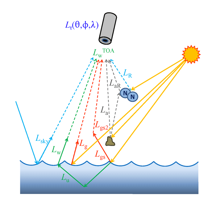
The atmospheric contribution in Eq. (1), usually called atmospheric path radiance, comes from scattering by atmospheric gases and aerosols, including multiple scattering between gases and aerosols. The path radiance that comes solely from scattering by atmospheric gas molecules is usually called the Rayleigh radiance, , because scattering by molecules is well described by the Rayleigh mathematical model of scattering by particles that are much smaller than the wavelength of light. In the absence of any aerosols, the atmospheric path radiance would equal the Rayleigh radiance. Let denote the aerosol contribution, which is the path radiance that would occur if the atmosphere consisted only of aerosol particles. Let denote the contribution resulting from multiple scattering between aerosols and gases. The total surface reflectance can be separated into a contribution due to direct Sun glint from the water surface, ; by background sky radiance reflected by the water surface, ; and by Sun and sky radiance reflected by whitecaps and foam, . Thus Eq. (1) can be further partitioned into
| (2) |
In practice, the aerosol and aerosol-gas contributions are usually grouped together and treated as one contribution, sometimes denoted and often called just the aerosol contribution. The sky reflectance term is accounted for as part of the Rayleigh correction, which incorporates reflectance by the sea surface. For some sensors that were specifically optimized for ocean color (e.g., CZCS and SeaWiFS), the strongest part of the Sun glint (the Sun’s glitter pattern) is avoided by pointing the sensor in a direction away from the Sun so that almost no direct glint is present in the image. However, there is still a correction for residual amounts of Sun glint. Figure 1 illustrates these contributions to the TOA radiance.
Most papers (e.g., Wang and Bailey (2001), Wang (2002)) rewrite Eq. (2) as
| (3) |
or something very similar. Now, however, , , and are all measured at sea level. is the direct transmittance between the sea surface and the TOA along the viewing direction, and is diffuse transmittance in the viewing direction. These transmittances are discussed on the Atmospheric Transmittances page.
Yet a third formulation can be found in the literature (e.g., Franz et al. (2007), Eq. 1):
| (4) |
Here is the diffuse transmittance along the viewing path of the sensor. is the transmittance by atmospheric gases in the viewing direction, and is the transmittance by atmospheric gases in the Sun’s direction; these transmittances are usually called gaseous transmittances. is a known instrument polarization-correction factor. Comparison of Eqs. (3) and (4) shows, for example, that
Thus the total TOA Rayleigh contribution has been factored into a product of terms involving a Rayleigh term times gaseous transmittances and a polarization-correction factor. The difference between Eqs. (3) and (4) is primarily a matter of simplification for presentation purposes. The term came into the nomenclature because MODIS has large polarization sensitivity and this requires correction. Earlier papers by Gordon and Wang often ignored the gaseous transmission terms because they were only considering ozone, which could be “taken off the top,” so to speak, with the remaining problem being effectively formulated below the ozone layer. The term is computed using a standard atmosphere and only non-absorbing gases and . This allows ”standard” Rayleigh radiances to be computed as a function of Sun and viewing geometry. The gaseous transmittances are computed by use of absorption coefficients, computed path lengths, and gas concentrations for the various gases. The term is computed for each image pixel as a function of atmosphere and surface polarization states (modeled Rayleigh and glint Stokes vectors) and the sensor-specific polarization sensitivity with viewing direction.
All of Eqs. (2), (3), and (4) can be found in the literature. They all give the same TOA total radiance . Which form is used in a particular instance is determined by convenience. Forms (2), (3) are often convenient for discussions of theory, whereas form (4) is convenient for operational atmospheric correction algorithms.
The goal of atmospheric correction is to convert a measured top-of-the-atmosphere radiance into the corresponding sea-level water-leaving radiance . Since only is measured, this requires estimation of the various atmospheric and surface-reflectance terms seen in Eqs. (3) or (4) so that they can be subtracted from in order to arrive at . How this is done is discussed in Level 2 of this Chapter.
 See comments posted for this page and leave your own.