Page updated:
March 13, 2021
Author: Collin Roesler
View PDF
Benchtop Spectrophotometry of Suspended Particulates
Benchtop Spectrophotometry of Suspended Particulate Matter Measured in Internally-mounted Cuvettes inside an Integrating Sphere (IS-mode)
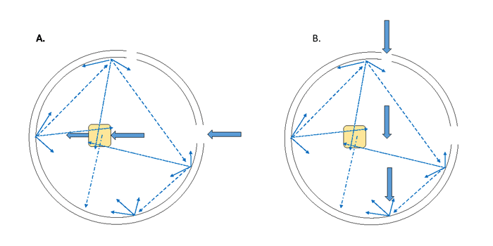
Measuring absorption of suspended particulate matter in benchtop spectrophotometers is much more challenging because they are not optimized to collect the scattered radiant power. Thus the measured transmitted radiant power is reduced by the amount of scattering, which is incorrectly attributed to absorption. The absorption coefficients therefore will be overestimated. For this approach an integrating sphere is employed. Interestingly, the history of the integrating sphere precedes that of the spectrophotometer by about 50 years. Integrating spheres are hollow spherical cavities coated with highly scattering interior surfaces designed to scatter light in a diffuse pattern (equal in all directions) while minimally absorbing light. Thus the result is to remove the effect of the directionality of the incident light so that transmitted radiant power can be measured from any small portion of the sphere (Fig. 1) and extrapolated to all of the light using geometric relationships. Scattered radiant power has the same likelihood of detection as transmitted radiant power; the only loss is due to absorption.
The challenge of the integrating sphere is to measure only the loss of incident radiant power that goes through the sample (thick arrows in Fig. 1A, called the sample beam) and not of the radiant power that has reflected from the sphere and re-enters the sample (thin arrows). This is achieve by slightly offsetting the sample cuvette from the reference beam (large arrows in Fig. 1B). In this way the reference beam and the sample beam generate identical light fields within the sphere with the exception of the directly transmitted sample beam. Thus by difference, the contribution to the loss of the sample beam due to multiple scattering through the sample is removed (as it shows up in both the transmitted reference and transmitted sample beams).
Similar to the protocol for transmission mode measurements of non-scattering solutions, either a baseline scan is collected with reference material in the cuvette, a zero scan is collected, followed by 3-5 blank scans for automatic baseline correction, or the 3-5 blank scans are first collected and the samples are corrected in post processing. In either case, the alternating sequence of 5-6 sample scans and a blank scan are collected. Absorption coefficients are computed as before where the absorbance, , is given by
where is the measured reference beam through the sphere and is the sample beam through the sphere and all else is unchanged.
 See comments posted for this page and leave your own.