Page updated:
March 16, 2021
Author: Curtis Mobley
View PDF
From XYZ to RGB
Computer monitors and TVs have light sources made of many groups of three small pixels. One pixel in each group generates visually red light, one green, and one blue. Each group can generate various levels of brightness for each color. Computer monitors thus use a triplet of red, green, and blue (RGB) values to define how much of each primary color is used to generate a desired color. In most monitors, each value of R, G, or B ranges from 0 (no light of that color emitted; the pixel is turned off) to (maximum brightness). This is usually called “8 bit/channel” or “24 bit,” i.e. , color. These 256 brightness levels for each primary color give a total of different colors and levels of brightness that can be displayed, even though the human eye can perceive differences in far fewer colors and brightness levels. Digital cameras likewise store images in terms of RGB values.
As was seen on the Chromaticity page, converting a spectrum into CIE and then into chromaticity values is easy. Converting between and values is more complicated.
From CIE XYZ to RGB Values
The personal computer (PC) industry (Microsoft and Hewlett Packard in particular, see Stokes et al., 1996) defined an RGB color model or color space, i.e. a gamut of colors, for use with PC monitors. This color model, called sRGB, is the gamut of colors that can be generated on most PC computer monitors. (Not surprisingly, Apple has its own color model, as does Adobe, and there are at least a dozen others.)
The conversion from CIE XYZ to sRGB coordinates is given by
| (1) |
In this equation, the values are assumed to be scaled from 0 to 1. The conversion matrix seen here comes from the excellent web site maintained by Bruce Lindbloom. The Lindbloom web site gives all of the details about color spaces and conversions from one color space to another, including online calculators and downloadable spreadsheets for doing various calculations.
Now consider CIE reference illuminant E, which is pure white, with equal energy at each wavelength. Setting for all gives a values of for each of , and . Rescaling these values to 1 and using them in Eq. (1) gives , which can be rescaled to . This result is not as might be expected for a pure white color. The computed RBG color is actually a pale red or pink. The reason for this color mismatch is that sRBG is based on the D65 reference illuminant, whereas the CIE 1931 chromaticity diagram uses reference illuminant E to define “white.”
If we let be the normalized D65 spectrum seen in the last figure of the Chromaticity page, then . Rescaling these values to a maximum value of 1 and inserting them into Eq. (1) then returns each of , and as 0.918. Multiplying these values by 255 rescales them to , which is a very light gray. Keep in mind that gray is just white that is not very bright, so these values can be rescaled to without changing the color. Thus the sRBG color model returns the D65 illuminant as the white color, and it returns the equal-energy spectrum E as a pink color.
The conversion from sRGB values to XYZ is given by the inverse of Eq. (1):
| (2) |
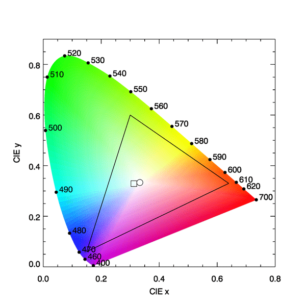
The RGB values in Eq. (2) are considered to be between 0 and 1. If we rescale to and insert into this equation, it returns , which gives the CIE chromaticity coordinates . This is the slightly bluish color of the D65 spectrum shown by the box symbol in Fig. 1.
Using Eq. (2) to convert gives , which gives . Converting (0, 1, 0) gives , and (0, 0, 1) gives . These three (x,y) values define the vertices of the sRBG gamut triangle seen in Fig. 1. It is clear that this gamut cannot accurately reproduce many of the colors visible to the eye (nor can any of the other gamuts used in computer montors and TVs). Indeed, the sRGB color space represents only 35% of the entire CIE (x,y) color space. In other words, only 35% of the colors as seen by the human eye can be accurately reproduced on a computer monitor using the sRBG color model.
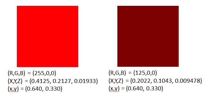
It was mentioned on the Color Vision page that “brown is just red that is not very bright.” Figure 4 of that page showed a sequence of color patches that were generated by turning on only the red pixels of a monitor, but with decreasing intensities. The perceived color went from bright red for to a dark reddish brown for . Those two color patches are reproduced in Fig. 2. If the RGB values for these two color patches are rescaled to (1,0,0) and (0.49,0,0), respectively, and inserted into Eq. ( 2), the resulting CIE chromaticities are the same for each: . What is different is the luminance: for the bright red patch, and for the dark brown patch. It is likely that most people would call these patches different colors, but in the language of color science, they are the same color but different brightnesses (same chromaticity but different luminances).
There are additional complications to mention in the conversion from XYZ to RGB color specifications.
First, the eye does not respond in a linear fashion to differences in brightness. In particular, the eye is more sensitive to differences in darker color tones than it is to differences in brighter tones. Therefore, a linear spacing of RGB values allocates more of the 0-255 range to high values, which the eye cannot distinguish well, than to low values where the eye sees greater differences for a the same difference in RGB values. Therefore, after using Eq. (1) to obtain “linear” RGB values, is it customary to apply a gamma correction to the result. A gamma correction is a non-linear “stretching” of the RGB values so as to make better use of the limited range of values (usually 0 to 255) available for storing the color information. The gamma correction for the sRGB color model is given by
The same transformation is applied to the G and B values. Here the gamma value is . After this gamma correction, an input of results in rather than the values of (255, 201, 192) found above using only Eq.(1). Conversely, if gamma-corrected RGB values are to be converted to XYZ values, the gamma correction needs to be undone via
The same transformation is applied to the gamma-corrected G and B values. The resulting “linear” RBG values can then be used is Eq. 2.
Second, you often have to make a subjective decision on how to rescale the RGB values to get the right brightness when displayed. For example, Dierssen et al. (2006) found that scaling so that gave RGB values in the mid-range of brightness and reasonable screen colors from RGB values computed by Eq. (1). The value of 0.4 was an ad hoc choice determined by trial and error for visual appearance of ocean radiance spectra colors. As was seen in Fig. 2, the brighness affects the perceived color.
Third, note that the 3x3 transformation matrix in Eq. (2) has positive elements. Thus any triplet of positive numbers generates an triplet of positive numbers, i.e. a valid point in the CIE chromaticity diagram. That is to say, any RGB color can be represented on the CIE diagram. However, some of the matrix elements in Eq. (1) are negative. This means that not every valid or can be represented by valid values; some of the , and values may be negative. When that happens, about all you can do is set the negative value to 0 and hope that the displayed color is not too different from what your eye would see in nature.
Fourth, color reproduction gets even more complicated when printing. Computer monitors are emitting light, and various colors are generated by adding together different amounts of red, green, and blue light. Thus yellow is generated by turning on the red and green pixels. The RGB system is an additive color system. When viewing colors on a printed page, you are seeing reflected light. The dyes in the ink absorb, or subtract, various colors from the incident (usually white) light. The printing industry thus deals with subtractive colors, e.g., green is generated by subtracting (absorbing) blue and red from white. Color printers thus use the CMYK (cyan, magenta, yellow, black) subtractive color system, which specifies how much ink of various colors to put onto the page, rather than how much light to generate. Some printers have additional ink colors. Thus the color space or gamut for a printer, when plotted on a CIE diagram, will have more than three vertices if the printer uses more than three colors of ink. This can give better coverage of the human vision color space than can a three-color RGB system. Needless to say, converting a computer screen image from RGB to CMYK values is a messy business, and full account of the reference illuminants and color models for the monitor and the printer must be taken into account. This is what is done in PhotoShop, for example, when you do a “save as CMYK” on an RGB jpeg file. The resulting printed image may or may not be satisfactory, depending on whether or not the underlying color models are consistent with the printer to be used.
The HydroLight radiative transfer model computes the values for , and whenever the run covers at least the 400-700 nm range. These quantities are uniquely determined for each spectrum. However, HydroLight does not attempt to compute corresponding RGB values because those values are device dependent and may require subjective scaling to get good color reproduction. If you want to turn your spectra into RGB or CMYK values, you can start with the HydroLight-computed values, but beyond that you are on your own. Note that given , you can recover from
where Y is in the range [0, 1].
This is enough to say about colors. This page barely gets you started into the very complicated business of color management and rendering on specific monitors or printers. The previously mentioned web site maintained by Bruce Lindstrom is an excellent place to start if you wish to dig deeper into these topics.
 See comments posted for this page and leave your own.