Page updated:
May 18, 2021
Author: Curtis Mobley
View PDF
The SRTE: Heuristic Development
This page presents a heuristic or qualitative derivation of the the scalar radiative transfer equation (SRTE). The end results (Eqs. (9), (10), or (12)) are correct, but the steps of the derivation are physically incorrect because polarization is ignored. In addition, the derivation of this page gives no way to estimate the errors that result from ignoring polarization. Nevertheless, this form of the derivation of the SRTE is found is almost every textbook and it does serve as a useful way to remember the various physical processes that contribute to light propagation in an absorbing and scattering medium like the ocean or atmosphere. This derivation is also of historical interest because it shows how the founding fathers of radiative transfer theory proceeded in order to obtain a governing equation (e.g., Preisendorfer (1965), page 65) before the link between fundamental physics and radiative transfer theory was firmly established.
The Level 2 pages beginning at The General Vector Radiative Transfer Equation outline the steps of a physically rigorous derivation of various levels of RTEs, ending with the SRTE seen below.
Radiative Processes
To the extent that polarization can be ignored, the SRTE expresses conservation of energy written for a collimated beam of radiance traveling through an absorbing, scattering and emitting medium. We thus begin by considering the various processes that can occur when light interacts with an atom or molecule.
The light (electromagnetic radiation) may be annihilated, leaving the atom or molecule in an excited state with higher internal (electronic, vibrational, or rotational) energy. All or part of the absorbed radiant energy may be subsequently converted into thermal (kinetic) or chemical energy (manifested, for example, in the formation of new chemical compounds during photosynthesis). The annihilation of the light and conversion of its energy into a nonradiant form is called absorption. (See The Physics of Absorption page for further discussion of the quantum mechanics of absorption processes.) If the molecule almost immediately (on a femtosecond () or shorter time scale) returns to its original internal energy state by re-emitting radiation of the same energy as the absorbed radiation (but probably traveling in a different direction from the original radiation), the process is called elastic scattering. Because of the extremely short time required for these events, elastic scattering can reasonably be thought of as the light interacting with the molecule and simply “changing direction” without an exchange of energy with the scattering molecule.
The excited molecule also may emit radiation of lower energy (longer wavelength) than the incident radiation. The molecule thus remains in an intermediate excited state and may at a later time emit new radiation and return to its original state, or the retained energy may be converted to thermal or chemical energy. Indeed, if the molecule is initially in an excited state, it may absorb the incident light and then emit light of greater energy (shorter wavelength) than the absorbed light, thereby returning to a lower energy state. In either case the scattered (emitted) radiation has a different wavelength than the incident (absorbed) radiation, and the processes is called inelastic scattering. One important example of this process in the ocean is Raman scattering by water molecules. Fluorescence is an absorption and re-emission process that occurs on a time scale of to . If the re-emission requires longer than about , the process is usually called phosphorescence. The physical and chemical processes that lead to the vastly different times scales of Raman scattering vs. fluorescence vs. phosphorescence are much different. The distinctions between the very short time scale of Raman “scattering” versus the longer time scale of fluorescence “absorption and re-emission” do not concern us in the derivation of the time-independent RTE. However, the terminology has evolved somewhat differently, e.g., Raman scattering usually refers to “incident” and “scattered” wavelengths, whereas fluorescence usually refers to “excitation” and “emission” wavelengths.
The reverse process to absorption is also possible, as when chemical energy is converted into light; this process is called emission. An example of this is bioluminescence, in which an organism converts part of the energy from a chemical reaction into light.
In order to formulate the RTE, it is convenient to imagine the total light field as many beams of electromagnetic radiation of various wavelengths coursing in all directions through each point of a water body. We then consider a single one of these beams, which is traveling in some direction and has wavelength . This beam and the processes affecting it are illustrated in Fig. 1.
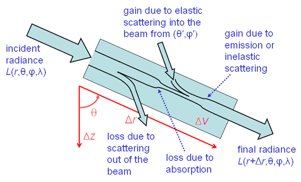
Now think of all the ways in which that beam’s energy can be decreased or increased. Bearing in mind the preceding comments, the following six processes are both necessary and sufficient to write down an energy balance equation for a beam of light on the phenomenological level:
- Process 1
- loss of energy from the beam through annihilation of the light and conversion of radiant energy to nonradiant energy (absorption)
- Process 2
- loss of energy from the beam through scattering to other directions without change in wavelength (elastic scattering)
- Process 3
- loss of energy from the beam through scattering (perhaps to other directions) with change in wavelength (inelastic scattering)
- Process 4
- gain of energy by the beam through scattering from other directions without change in wavelength (elastic scattering)
- Process 5
- gain of energy by the beam through scattering (perhaps from other directions) with a change in wavelength (inelastic scattering)
- Process 6
- gain of energy by the beam through creation of light by conversion of nonradiant energy into radiant energy (emission)
Next we must mathematically express how these six processes change the radiance as the beam travels a short distance in passing through a small volume of water, which is represented by the blue rectangle of Fig. 1.
Processes 1 and 3. It is reasonable to assume that the change in radiance while traveling distance due to absorption is proportional to the incident radiance, i.e., the more incident radiance there is, the more is lost to absorption. Thus we can write
| (1) |
Here denotes the change in between and . The minus sign is necessary because the radiance decreases (energy is disappearing, so is negative) along . Referring back to Eq. (1) on the Inherent Optical Properties page, it is easy to see that the present Eq. (1) is just the definition of the absorption coefficient written as a change in radiance over distance , rather than as a change in absorptance. Thus the proportionality constant in Eq. (1) is just the absorption coefficient as defined on the IOP page. Note that absorption at the wavelength of interest accounts both for energy converted to non-radiant form (absorption) and for energy that disappears from wavelength and re-appears at a different wavelength (inelastic scattering). Either process leads to a loss of energy from the beam at wavelength .
Process 2. In a similar fashion, the loss due to elastic scattering out of the beam direction into all other directions can be written as
| (2) |
where is the scattering coefficient as defined on the IOP page.
Process 4. This process accounts for elastic scattering from all other directions into the beam direction . Figure 2 shows Fig. 1 redrawn to illustrate scattering along path length from one direction into the direction of interest. These incident and final directions correspond to scattering angle as shown in Fig. 2.
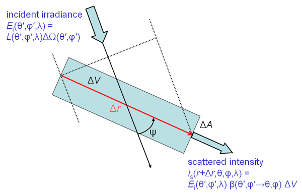
Recalling from Eq. (2) of the IOP page that one definition of the volume scattering function is scattered intensity per unit incident irradiance per unit volume, we can write
| (3) |
Here is the intensity exiting the scattering volume at location in direction . All of this intensity is created along by scattering from direction into , so = . The incident irradiance is computed on a surface normal to the incident beam direction, as illustrated by the dotted lines in Fig. 2. We can rewrite as the incident radiance times the solid angle of the incident beam:
| (4) |
Next recall from the Geometrical Radiometry page that intensity is radiance times area. Thus the intensity created by scattering along pathlength and exiting the scattering volume over an area can be written as
| (5) |
where is the radiance created by scattering along and exiting the scattering volume over a surface area . Using Eqs. (4) and (5) in (3) and writing the scattering volume as gives
| (6) |
This equation gives the contribution to by scattering from one particular direction . However, ambient radiance may be passing through the scattering volume from all directions. We can sum up the contributions to from all directions by integrating the right hand side of Eq. (6) over all directions,
| (7) |
where we have written the element of solid angle in terms the angles using Eq. (6) from the Geometry page.
Processes 5 and 6. Process 5 accounts for radiance created along pathlength in direction at wavelength by inelastic scattering from other all other wavelengths . Each such process, such as Raman scattering by water molecules or fluorescence by chlorophyll or CDOM molecules, requires a separate mathematical formulation to specify how radiance is absorbed from an incident beam at wavelength and converted to the wavelength of interest.
Process 6 accounts for radiance created de novo by emission, e.g. by bioluminescence, and each emission process again requires a separate formulation to define how the light is emitted as a function of location, direction, and wavelength. Those detailed formulations can be complex and will be treated elsewhere (pages under development). For the moment, we can simply include a generic source function that represents creation of radiance along pathlength in direction at wavelength by any inelastic scattering or emission process. Thus we write just
| (8) |
without specifying the mathematical form of the source function S.
We can now sum of the various contributions to the changes in L along . We can also take the conceptual limit of and write
Standard Forms of the RTE
The net change in radiance due to all six radiative processes is the sum of the right hand sides of Eqs. (1), (2) , (7), and (8). We thus obtain an equation relating the changes in radiance with distance along a given beam direction to the optical properties of the medium and the ambient radiance in other directions:
This is one form of the SRTE, written for changes in radiance along the beam path.
In oceanography, it is usually convenient to use a coordinate system with the depth being normal to the mean sea surface and positive downward. Thus depth is a more convenient spatial coordinate than location along the beam path. Changes in are related to changes in as shown in Fig. 1: . Using this in Eq. (9), assuming that the ocean is horizontally homogeneous, and recalling that , we get
This equation expresses location as geometric depth and the IOPs in terms of the beam attenuation and the volume scattering function .
Other forms of the RTE are often used. The nondimensional optical depth is defined by
| (11) |
Dividing Eq. (10) by and using (11) gives the SRTE written in terms of optical depth. It is also common to use as the polar angle variable. Recalling Eq. (7) of the Volume Scattering Function page, we can factor the volume scattering function into the scattering coefficient times the scattering phase function . Finally, recalling the definition of the albedo of single scattering , we can re-write Eq. (??) as
This equation now shows all quantities as a function of optical depth.
Any of Eqs. (9), (10), or (12) is called the monochromatic (1 wavelength), one-dimensional (the depth is the only spatial variable), time-independent SRTE.
Form (12) of the SRTE yields an important observation: In source-free () waters, any two water bodies having the same single-scattering albedo , phase function , and boundary conditions (including incident radiances) will have the same radiance distribution at a given optical depth. This is why optical depth, albedo of single scattering, and phase function are often the preferred variables in radiative transfer theory. Note, for example, that doubling the absorption and scattering coefficients and leaves unchanged, so that the radiance remains the same for a given optical depth. However, the geometric depth corresponding to a given optical depth will different after such a change in the IOPs.
We can convert geometric depth to optical depth, or vice versa, by integrating Eq. (11):
| (13) |
Note that the optical depth corresponding to a given geometric depth is usually different for different wavelengths, because the beam attenuation depends on wavelength. This is inconvenient for oceanographic work, so Eq. (10) is usually the preferred form of the SRTE for oceanography.
We have now derived the SRTE in a form adequate for much oceanographic work. Technically, the SRTE is a linear integrodifferential equation because it involves both an integral and a derivative of the unknown radiance. This makes solving the equation for given IOPs and boundary conditions quite difficult. Fortunately, the radiance appears only to the first power. Nevertheless, there are almost no analytic (i.e., pencil and paper) solutions of the SRTE except for trivial special cases, such as non-scattering waters. Sophisticated numerical methods therefore must be employed to solve the SRTE for realistic oceanic conditions.
As mentioned at the start, the development on this page has been for unpolarized light. In a sense, this is always incorrect because polarization is an inherent property of electromagnetic waves (light in particular). Even if the incident beam is unpolarized, scattering (either by particles within the water or by reflection and transmission by the air-water surface) induces polarization. Thus underwater radiance in a particular direction is usually at least partially polarized. Nevertheless, the unpolarized, or scalar RTE (SRTE), derived here gives sufficiently accurate solutions for many (but not all) oceanographic applications. There are three main reasons for the utility of the SRTE in underwater optics:
- The particles responsible for scattering within the ocean are usually much larger than the wavelength of light. Polarization by scattering is greatest for particles much smaller than the wavelength (for example, Rayleigh scattering by water molecules). The larger the particle, the less polarization is induced by scattering of unpolarized sun light.
- Multiple scattering is almost always significant underwater. Multiple scattering tends to depolarized the radiance, i.e., reduce the overall degree of polarization induced by single scattering events.
- Irradiances are often the radiometric quantity of interest. Irradiances are computed from integration of the radiance over direction, which tends to average out different polarizations in different directions.
However, if very accurate results are needed (e.g., radiance with an error of less than 10% in a given direvction), or if the state of polarization itself is of interest, then a polarized or vector RTE (VRTE), must be used. The VRTE is more complicated than the SRTE developed here. The Level 2 page on The VRTE develops the VRTE in a form suitable for oceanography.
 See comments posted for this page and leave your own.